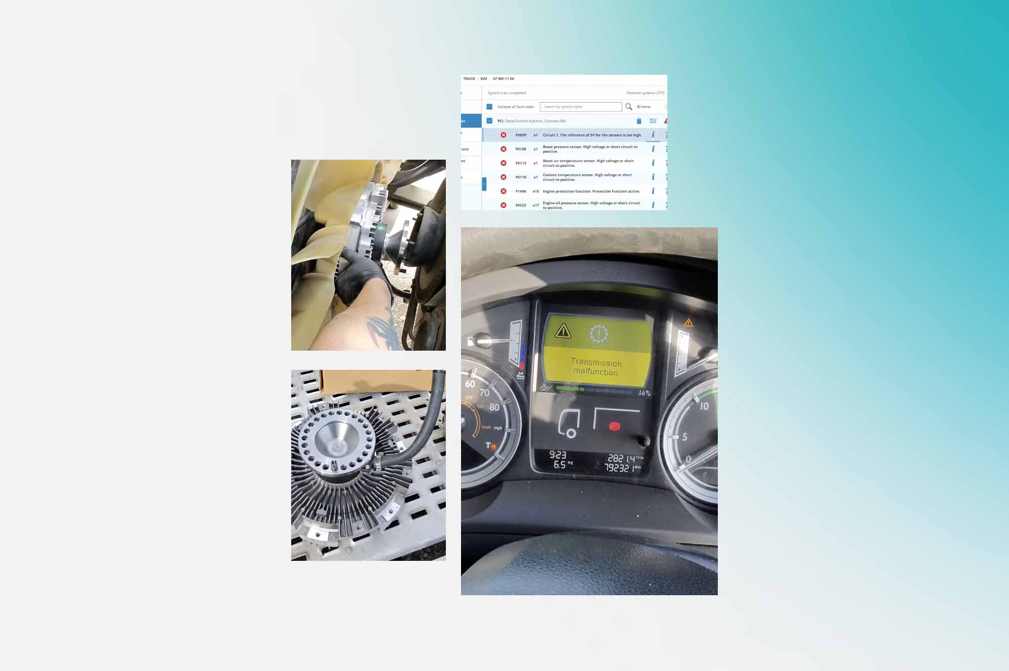


Commercial vehicles such as heavy-duty trucks are intricate machines that rely on multiple integrated systems working together. When a fault occurs, it triggers a diagnostic trouble code (DTC) that points to the source of the problem. Understanding and interpreting fault codes is a critical skill for commercial vehicle technicians.
Major truck manufacturers use their own formatting and terminology for codes but have many common DTCs across makes and models. By becoming well-versed in the most prevalent commercial vehicle fault codes, technicians can rapidly pinpoint issues for expedited diagnosis and repair.
In this article, we will explain the most prevalent fault codes for leading commercial vehicle manufacturers. Whether caused by sensor failures, emission control malfunctions, or ECU problems, we’ll provide an overview of codes technicians frequently encounter. With Jaltest CV and knowledge of these major OBD-II and manufacturer-specific DTCs – commercial vehicle repair professionals can diagnose problems quickly and maximize uptime. Keep reading as we break down key codes used by Mercedes, MAN, Scania, DAF, Volvo, and Iveco.

🔴 0C1112 : A regeneration request to test the AdBlue® quality was detected.
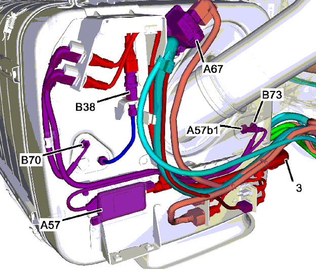
Legend:
- A57 (NOx sensor control unit, exhaust aftertreatment unit outlet)
- A57 b1 (NOx sensor, exhaust aftertreatment unit outlet)
- A67 (AdBlue® metering device)
- B38 (Exhaust pressure sensor downstream of diesel particulate filter)
- B70 (Exhaust temperature sensor downstream of diesel particulate filter)
- B73 (Exhaust temperature sensor downstream of SCR catalytic converter)
- 3: Wiring harness Vehicle
Possible causes of the fault
- Excessively high nitrogen oxide emissions due to low AdBlue® quality
- If there are no complaints, troubleshooting is not necessary.
- If fault code 0C1101 is current, process this fault first.
Instructions
- If other fault codes are stored in the control unit, process these first.
- Read out fault memory of control unit ‘A4 (Engine management (MCM) control unit)’ and process fault codes.
❓ Question – Are current fault codes present?
NO –
Instructions
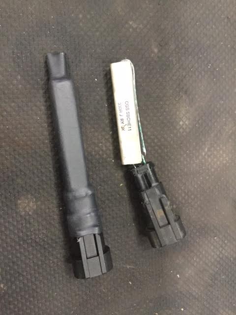
- Check components ‘A57 b1 (NOx sensor, exhaust after-treatment unit outlet)’ and ‘A70 b1 (NOx sensor, exhaust after-treatment unit inlet)’ for proper installation.
Note
- A57 b1 (NOx sensor, exhaust after-treatment unit outlet) ( Gray )
- A70 b1 (NOx sensor, exhaust after-treatment unit inlet) ( Black )
❓ Question – Are the components ‘A57 b1 (NOx sensor, exhaust after-treatment unit outlet)’ and ‘A70 b1 (NOx sensor, exhaust after-treatment unit inlet)’ correctly installed?
YES –
Instructions
- Check AdBlue® quality in the AdBlue® tank.
- Check AdBlue® for dilution.
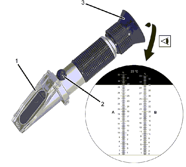
Note
- If the area content is below 30 %, the entire AdBlue® quantity should be replaced.
❓ Question – Is the AdBlue® quality OK?
YES –
Instructions
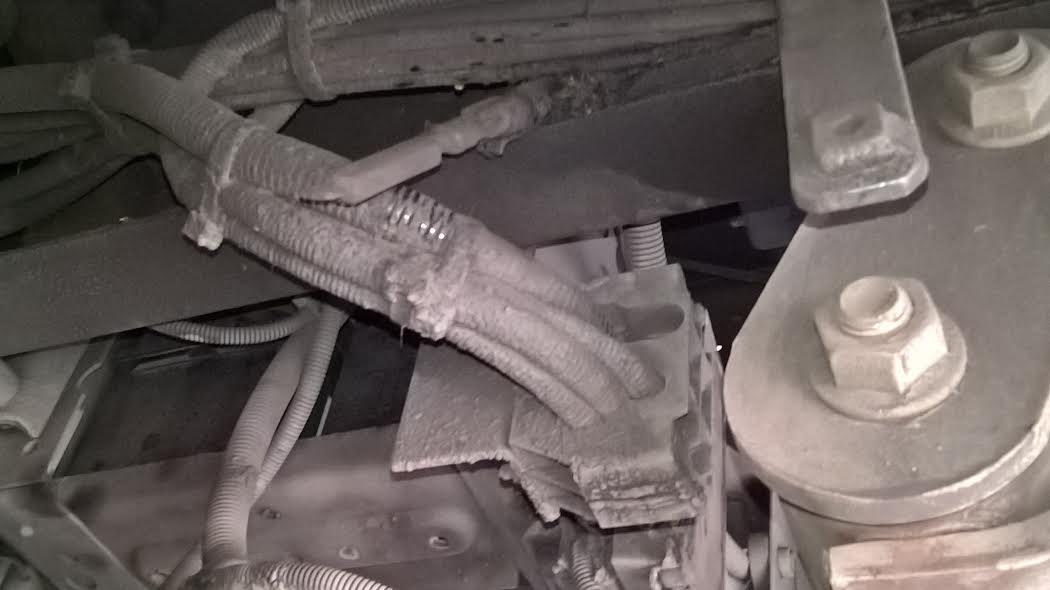
- Visually inspect component ‘A67 (AdBlue® metering device)’ and the hydraulic AdBlue® lines for leakage.
Legend:
- A58 (Pump module)
- A67 (AdBlue® metering device)
- B74 (AdBlue® fill level sensor/temperature sensor)
- R6 (AdBlue® return line heating element)
- R7 (AdBlue® intake line heating element)
- R8 (AdBlue® pressure line heating element)
- Y627 (AdBlue® heater coolant solenoid valve)
- 1: Coolant line
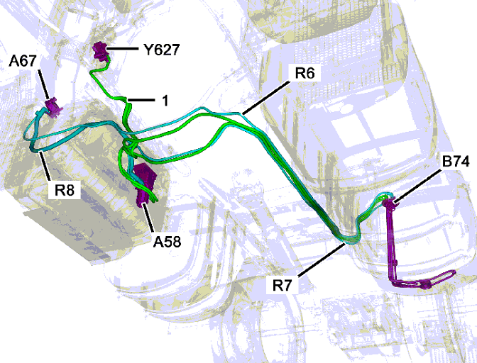
❓ Question – Is there a visible leak at component ‘A67 (AdBlue® metering device)’ and at the associated AdBlue® pressure lines?
NO –
- Perform a leak test.
❓ Question – Is leakage visible at the component ‘A67 y3 (AdBlue® metering valve)’?
NO –
- Perform test Metering amount.
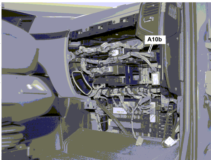
🔴 76020C: Component ‘A10b (Electronic brake control (EBS) control unit)’ has an internal fault.
Possible causes of the fault
- Component ‘A10b (Electronic brake control (EBS) control unit)’ is defective.
- The power supply for component ‘A10b (Electronic brake control (EBS) control unit)’ is not OK.
Tests
- Inspect cables, connectors, electrical connections and components for damage, correct connection, loose contact and corrosion and repair if necessary.
- Read out fault memory of component ‘A10b (Electronic brake control (EBS) control unit)’ and process error codes.
- Erase fault memory.
Instructions
- Switch off the ignition.
- Replace control unit ‘A10b (Electronic brake control (EBS) control unit)’ in accordance with the repair instructions.
- Reconnect all separated electrical connectors.
- Check the coding in control unit ‘A10b (Electronic brake control (EBS) control unit)’ and correct it if necessary.
- Perform function check.
End of test
- Erase fault memory.
Legend
- A10b (Electronic brake control (EBS) control unit)

🔴 SPN 3929: SENSING SYSTEM with LAMBDA PROBE EGR (glitch)
Indication of the defect:
- No (priority 4)
- For vehicle operating tests: the Central indicator of faults during the drive or parking a vehicle permanently lit in yellow (priority 5)
- OBD fault-P2BAD, MIL light is on
Monitoring strategy:
- Sensing the NOx control system through the lambda
Effects of glitches:
- When it comes through the sensing probe to detect the lambda too low grade and thus to determine the AGR too high concentrations of NOx, to request MILES
Description of the defect:
- FMI 1: request miles without the conclusion of the AGR
- FMI 2: request MILES with a closed system of AGR
- FMI 8: request MILES directly from a closed system AGR
- FMI 9: request MILES directly from the faulty system AGR
Note:
- The deficiencies with relevance to NOx here include defects that cause bad or inactive exhaust gas re-circulation. Depending on the limit values and the Statute of the AGR will decide whether only blink miles or additionally must reduce performance.
After the removal of the defects of the system delete the contents of memory defects of EDC. Call using the MAN-cats® function “Reset flashing MIL and torque reduction”. Then turn off the ignition. After the phase of the EDC (max length of 5 seconds), the control unit can be switched on again. Flashing MILLION, respectively reduction of torque is so. It also deletes the corresponding “normal” record defects. Long-term memory defects are purged. Memory fault record is retained for a period of 400 days or 9600 hours of operation and then, if the defect does not already exist, automatically clears.
Exception: Fixed the glitch P2BAE, which is caused due to an error of communication on the CAN between the EDC and the AdBlue system or electrical defects lambda/end stage, disappears from long-term memory defects immediately, as soon as the fault will cease to exist!
Respect the wiring diagrams of the vehicle.
Measurement of the Removal of Defects:
- EGR
- See Troubleshooting
- See the SPNMAN 3929 3853
- EDC Control Unit
- Check Current Topics
- Delete or newly install functional parameter (SFP)
- Do the flash control unit
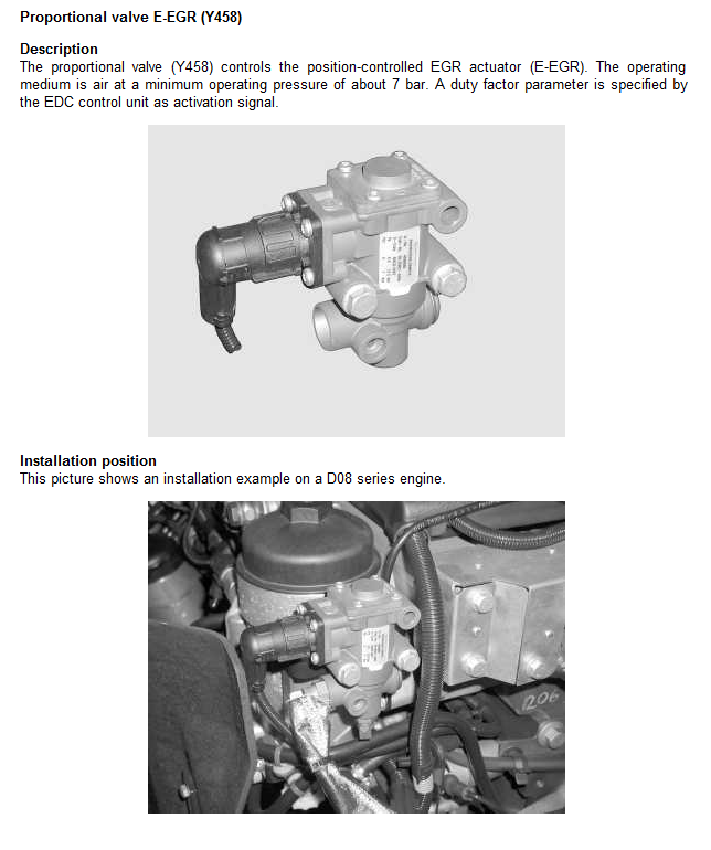
🔴 SPN 3853 STEADY-STATE DEVIATION E-EGR
Fault display:
- Central fault lamp shows steady yellow light when stationary (priority 3)
Monitoring strategy:
- Monitoring of the EGR flap position for permanent control deviation
Effect of fault:
- The output of a default value for the signal output value, switch-off of control
Cause of fault:
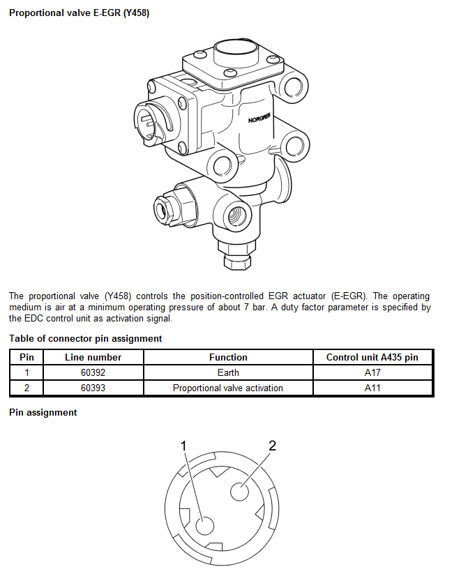
- Proportional valve E-EGR defective
| Testing | Measurement | Correcting the fault |
| Proportional valve E-EGR |
|
|
🔴 SPN 3938: LAMBDA PROBE is NOT ADAPTABLE
Indication of the defect:
- The central fault indicator while driving or parking a vehicle the yellow light is on permanently (priority 5)
Monitoring strategy:
- Control shooting too high or too low is the correction factor.
Description of the defect:
- FMI 1: too big correction factor
- Swapping conductors Nernst voltage (black) wires on the PIN B30 and Virtual Earth (yellow) on the PIN or replace wires B23 Nernst voltage (black) wires on the PIN B30 and trimrového resistance (green) on the PIN B31 or wire break pumpovacího current (red) on the PIN B24
- FMI 2: correction factor is too small
- Confused conductor Nernst voltage (black) wire on the PIN B30 and Virtual Earth (yellow) on the PIN B23
- FMI 3: Spurious signal (the signal of the lambda sensor 2 is too strong)
- FMI 8: bad signal (signal on2 When inertia is too small
- A short circuit between pins/B24 B23/B30/B31 and B05/B08 and B05 B25 or PIN or confused pins B05/B23/B30 and B08
After the removal of the fault clear the contents of the fault memory (EDC and OBD). Start the engine and check the monitoring of the correction factor of the lambda sensor. When the value ranges between 890 and 1140, they are not needed any more things to do. If the value of the correction factor is approx. 8000 or -8000, loading must be carried out during the registration process of the lambda sensor.
Registration retrieval of the lambda sensor: take a test drive with the vehicle (coolant temperature > 70 ° c). Leave the vehicle on the road at a driving speed oscillating jet 60 km/h for 15 seconds and then accelerate again (lambda probe with Kalilbruje for coasting). If it goes longer than 15 seconds, the fault appears inertia 3938-02. Then, repeat the process and must be careful to maintain the time of 15 seconds.
“Motor, switch and turn the ignition on again. The value must lie in the range 890 and 1140. If not, repeat the process.
How to: “motor, switch off and again turn on the ignition. Select in the Select menu Diagnostics C32 BOSCH EDC 7 “initialising the lambda sensor correction factor”. Initialises the correction factor of the lambda sensor. Turn off and turn on the ignition again.
Please respect the wiring diagrams for that vehicle.
| Review | Measurement | Removal of defects |
| The Lambda Probe |
|
|
| The Control Unit |
|
|
The involvement of the lambda sensor connector pins:
| PIN | Number/colour wires | Function | PIN EDC control unit |
| 1 | 60183/red | Pump action stream | B24 |
| 2 | 60185/yellow | Virtual Earth | B23 |
| 3 | 60396/white | Switching the heating cycle heat probe (-) | B08 |
| 4 | 60397/grey | Supply voltage heater probes (+battery) | B05 |
| 5 | 60184/green | Spur (spur) | B31 |
| 6 | 60186/black | Nernst voltage | B30 |

🔴 14071 – High Split
Description
- Loss of acknowledgement.
Cause
- The fault could be due to a faulty position sensor, air leakage or a mechanical fault in the gearbox.
- Due to gearbox tolerances, fault codes may be generated despite there being no fault with the gearbox.
Notes
- The system retains the current gear position.
- On gearboxes with overdrive (GRSO), the solenoid valves for splitter gear are controlled the other way around compared to gearboxes with direct gear (GRS). When changing to high split the low split solenoid valve is activated and when changing to low split the high split solenoid valve is activated.
Action
- Test the different modes of OPC operation.
If the problem persists:
- Examine the split operation.
- If you do not find any fault, check the inner actuating shafts, forks and synchromeshes of the gearbox.
If the problem does not persist:
- Examine the split operation if fault codes have been generated repeated times or if the driver has experienced disruption.
- If necessary, examine the gearbox internally.
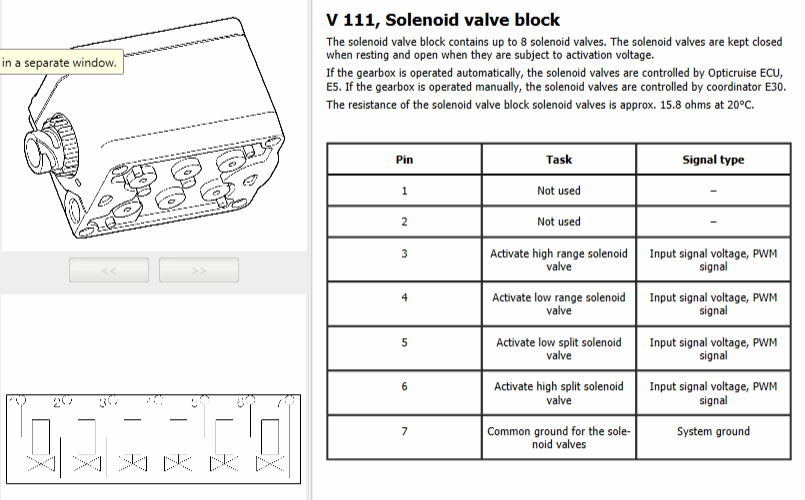
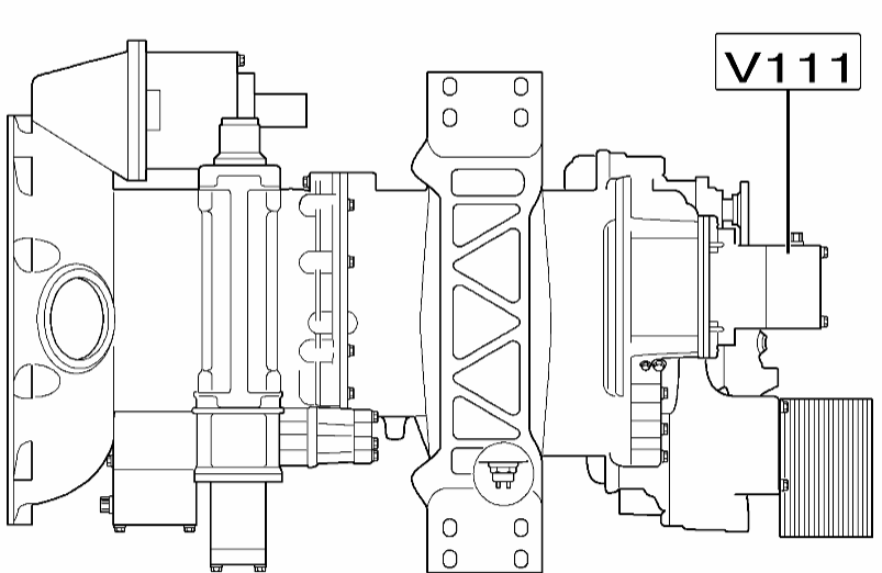
V111 – Solenoid valve block for split and range gear changing
- The solenoid valves in valve block V111 carry out gear changing between the low and high range and between the low and high split.
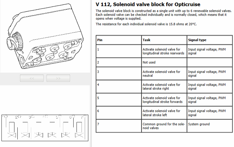
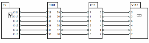
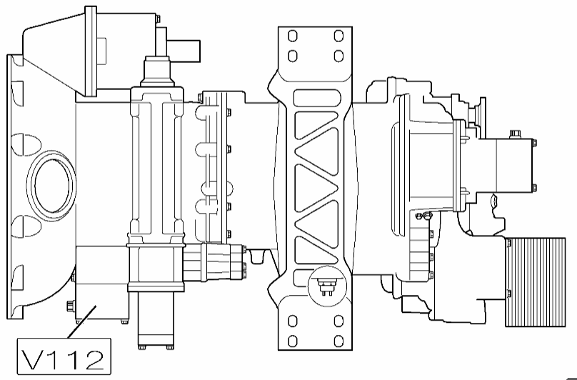
V112 – Solenoid valve block for Opticruise
- The Solenoid valve block for Opticruise V112 enables gear changing between lateral stroke left and right, between longitudinal stroke forward or rearward and changing to neutral.
🔴 Particulate filter 5803
Description
- The soot level in the particulate filter is deemed to be too high.
Cause
- Other fault codes that prevent regeneration are active.
- Manual regeneration has not taken place.
- Incorrect fuel quality.
- Fault in the differential pressure sensor CT141 across the particulate filter.
- Fault in exhaust gas temperature sensor CT158.
- Fault in the oxidation catalytic converter.
- Clogged oxidation catalytic converter.
- Fault in the measurement of gas flow, e.g. mass flow sensor CT126, charge air pressure sensor CT122.
- Fault in the exhaust gas recirculation.
- Fault in the injectors CV141-CV148.
- Fault in injection valve CV185.
- Too high a soot level in the particulate filter.
Notes
- Automatic and manual regeneration prevented.
- Increased fuel consumption.
- Poor output.
- High engine noise.
- The engine may run unevenly or shut down.
- Possible poor combustion efficiency leads to increased hydrocarbon emissions.
Action
- Rectify other fault codes related to the engine or exhaust system.
- If you suspect poor fuel quality, take a fuel sample and continue troubleshooting.
- Check the differential pressure sensor.
- Compare the CT158 temperature sensors. If a fault is detected in the above the fault has probably been rectified. Clear the fault codes and run Particulate filter regeneration.
- Disconnect the flexible hose to the silencer and check for visible smoke during throttle actuation with the neutral gear engaged. If there is visible smoke this indicates poor combustion due to an engine fault which has resulted in a full particulate filter.
- Check the exhaust gas recirculation, intake and exhaust system by running:
- function test EGR.
- Condition test on the variable geometry turbocharger.
- Check the injection system, Fuel system XPI.
- Check injection valve CV185 Exhaust gas after-treatment.
- Replace the particulate filter if no fault has been detected that clearly points to a problem with the measurement of the differential pressure across the particulate filter. Run Particulate filter regeneration, which also includes checking the oxidation catalytic converter.
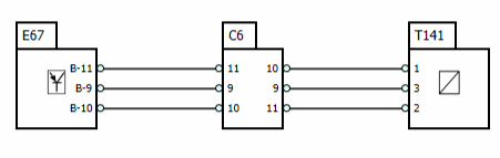
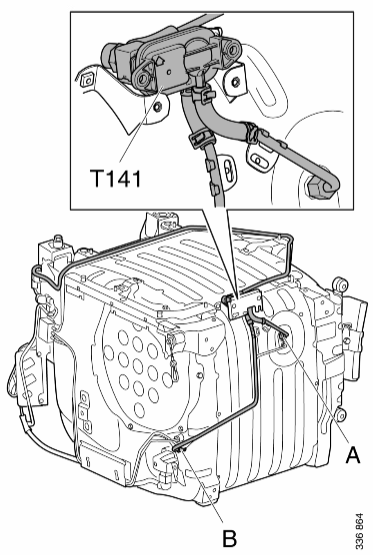
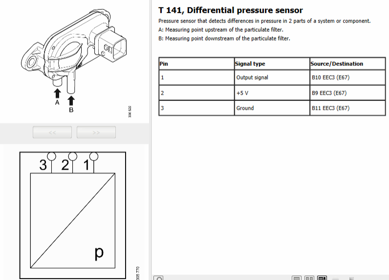
🔴 T141 – Differential pressure sensor
- The differential pressure sensor informs the control unit of pressure before and after the particulate filter in order to ensure that the particulate filter is whole and functional.
- When the engine is switched off the differential pressure should be between -10 mbar and +10 mbar.
- Check that the sensor signal varies during throttle application compared to idling – normally only a few mbar.
- If there is no variation, detach the hoses from the differential pressure sensor and carefully blow in the thicker pipe on the differential pressure sensor. Do not use pressure higher than 1 bar.
- Also, check for blockages in the pipes between the measurement points on the silencer and the differential pressure sensor. Detach the pipes at both ends and blow clean with compressed air.
- If there is a risk that the pressure sensor pipes may be frozen run the engine until the exhaust system has reached operating temperature at approximately 100°C, and check via temperature sensor T158 downstream of the oxidation catalytic converter.
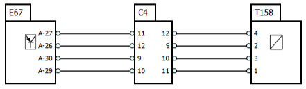
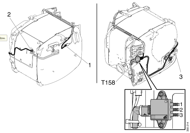
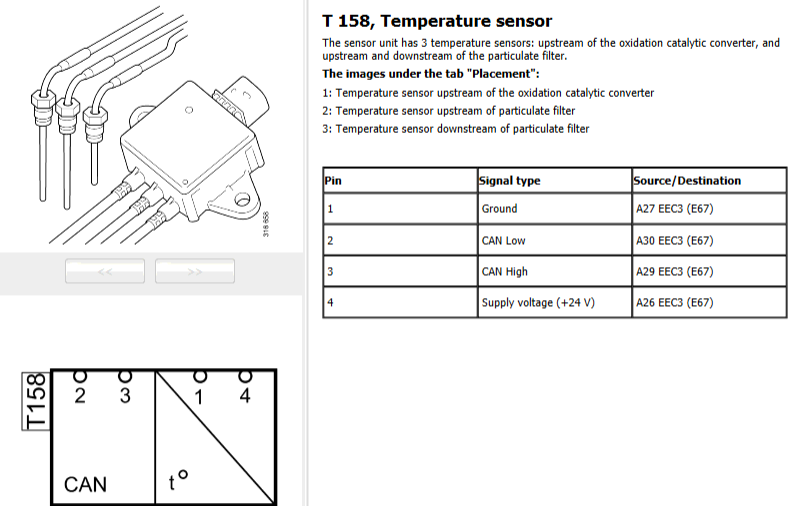
🔴 158 – Temperature sensor
- The temperature sensor measures the temperature upstream of the oxidation catalytic converter, and upstream and downstream of the particulate filter.
- The temperature sensor signal unit sends information on the temperature via CAN.
- Checking the temperature sensor
- Increase the engine speed to 1 500 rpm for 30 seconds, then run the engine at idling speed.
- Check that the values of the different temperature sensors change.
- Detach the temperature sensors from the silencer before the check.
- Check that the temperature sensors indicate about the same value when they are heated with a heat gun or hot water. The values of the various temperature sensors must not deviate from each other by more than 8°C.
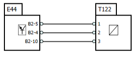
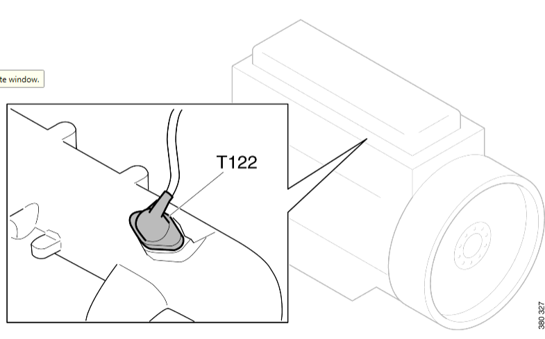
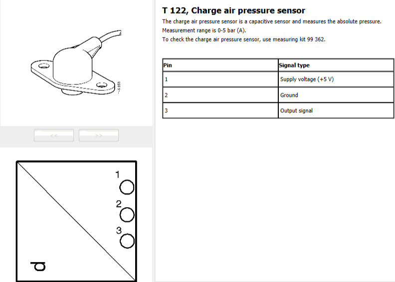
🔴 T122 – Charge air pressure sensor
The pressure sensor detects the absolute pressure in the intake manifold, i.e. the atmospheric pressure plus the positive pressure provided by the turbocharger. The pressure sensor then transmits a signal voltage to the engine control unit. The signal voltage is directly dependent on the charge air pressure.
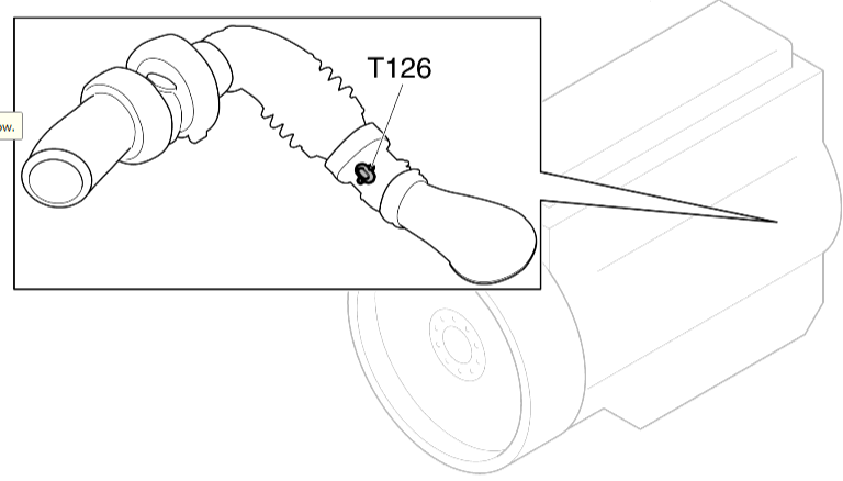
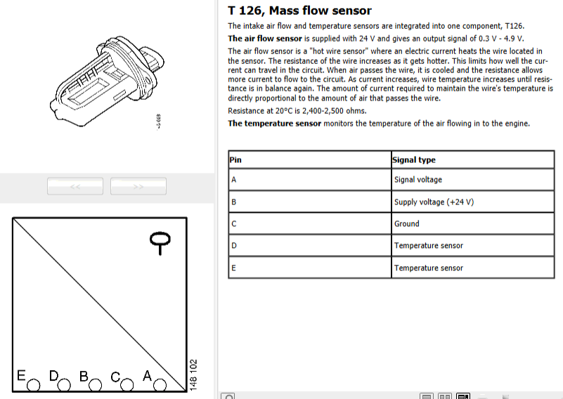
🔴 T126 – Mass flow sensor
- The mass flow sensor is positioned on the inlet pipe.
- The airflow sensor detects the quantity of air flowing into the engine. The airflow is measured in kg/min. The engine control unit uses the information to calculate the air-to-fuel ratio and to regulate EGR content.
- The temperature sensor monitors the temperature of the air flowing into the engine. The engine control unit also uses this information to calculate the air-to-fuel ratio since the oxygen content of the air varies with temperature.

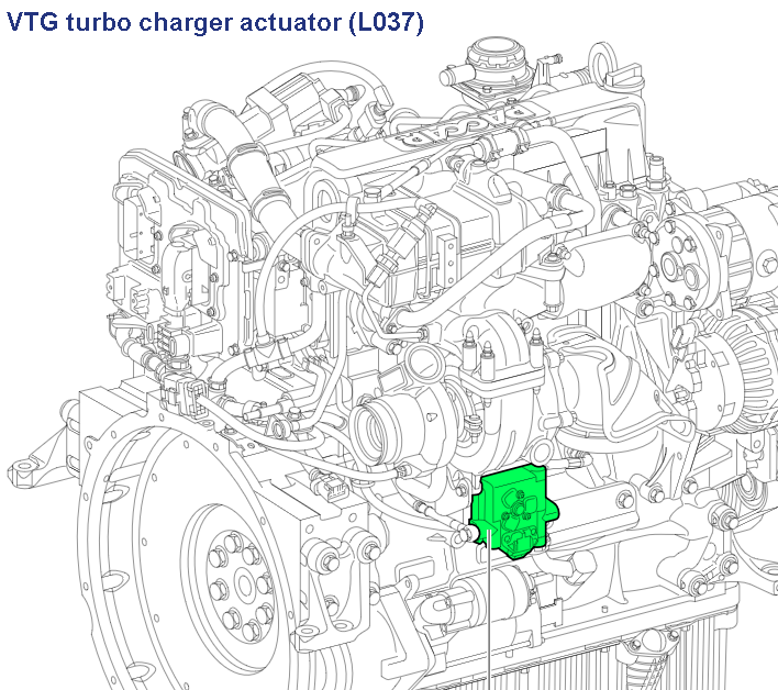
🔴 641-13 – VTG turbocharger actuator learning – Out of calibration
Set conditions
- The VTG actuator (L037) position was not known during the initial power-on.
Diagnostic condition
- This diagnostic runs 5 minutes after engine start-up if the engine coolant temperature is greater than 71°C.
Reset condition
- This DTC changes to INACTIVE after the diagnosis runs and passes.
Troubleshooting
- Checking data, VTG turbocharger actuator (L037)
- Location, VTG turbocharger actuator (L037)
Additional information
- This DTC can only be caused after the VTG actuator (L037) is removed or replaced, and then not installed correctly.
- When this DTC is ACTIVE:
- The VTG actuation is disabled.
- The EGR-valve operation is disabled.
- The engine torque is reduced if the engine is operated for an extended period of time with this fault ACTIVE.
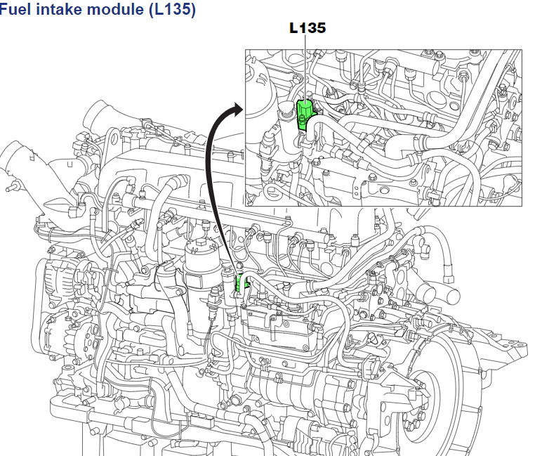
🔴 P3835, Fuel shut-off valve – Not responding or out of adjustment
Set conditions
- The EAS ECU detects that the fuel pressure sensor is reading a value lower than a threshold when the after-treatment fuel shut-off valve is opened.
Diagnostic conditions
- This diagnostic runs at the start of DPF regeneration.
Reset condition
The reset condition depends on the EAS software version:
- This DTC changes to inactive after the diagnostic runs and passes.
- This DTC remains active and must be erased with DAVIE before the diagnostic runs again.
Possible cause
- The fuel shut-off valve is stuck in a closed position.
- The fuel shut-off valve is clogged.
- Fuel pressure is too low in the engine fuel supply system.
- External leakage of the dosing supply pipe to the fuel dosing valve (L124).
Additional information
- The fuel shut-off valve is part of the fuel intake module (L135).
- The engine runs in protection mode.

🔴 MID 128 PSID 98 Boost air system
FMI 1
Below the set limit value.
Common faults are leaks and splits so please ensure all is good before inspecting the turbo
Conditions for fault code:
- Charge air pressure below the set limit value.
Possible cause:
- Leakage in the boost system.
- Faulty wastegate.
- Faulty turbocharger
Data valid but below the normal working range.
Possible cause:
- The turbo speed sensor may be faulty or be giving faulty indications to the turbo, thus decreasing pressure to a low charge pressure.
- The VGT shutter has fastened in a position with excessive opening, preventing pressure from building up and decreasing the turbine speed, thus lowering charge pressure.
Reaction from the control unit:
- The fault code is set.
- Charge pressure too low
- Turbocharger charging too little.
Noticeable external symptoms:
- Fault code requested.
- Reduced charge pressure.
Appropriate action:
- Active FMI
Start by turning off the ignition completely, when the ignition is turned on again listen for mechanical noises from the turbo. When the turbo starts, the shutter moves through its stroke to the end positions as a functional check. If it does not do this, it is probable that the shutter has fastened at one position.
Also –
IV – 1. Catalytic converter blocked
Customer Effect: Loss of performance, abnormal noise.
Fault Codes: Fault MID 128 PSID 98 FMI 1.
Actions:
- Check the catalytic converter input either visually or with an endoscope. Then put your hand (wearing protective gloves) into the input or output to check that the bricks will not move or have not moved (1).
Normal position of the bricks (green) Bricks out of position (red)
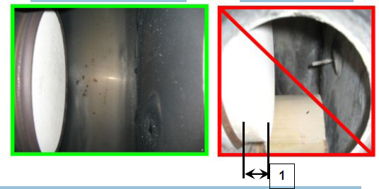
- During operation, check the temperature at the exhaust inlet (580°C maximum)
- Check that performance is normal:
- In the event of crystallisation at the catalytic converter inlet,
- If the bricks have moved (1), owing to the use of non-compliant AdBlue (sodium and/or potassium content too high), or because of a faulty catalytic converter, replace the catalytic converter.
🔴 P20EE00 – SCR NOx Catalyst Efficiency Below Threshold (Bank 1)
Event:
- Filtered NOx conversion below 58% and a filter is applied to the NOx conversion that may require the evaluation to be repeated a few times to set the fault. The time required depends on the engine load and the NOx flow. With all enable conditions fulfilled it normally takes no more than a few minutes.
Engine derate
Check:
- Reductant quality and concentration
- Exhaust leakage
- Sulphur poisoning
- Reductant delivery
- SCR catalyst
- Upstream NOx sensor
- Downstream NOx sensor

🔴 F9F00 – SCR INDUCEMENT WARNING TO THE DRIVER – ATTEMPTED TAMPERING – FAULT WARNING MESSAGE
Control Module: ECM – EDC17CV41
Context:
- Component: AD-BLUE METERING DEV MODUL
- Component: ENGINE DRIVE CONTROL.UNIT
- Visible fault: The MIL warning light is on and the DEF warning light flashes slowly.
Cause:
- The SCR Inducement fault warns the driver that it has been caused by attempted tampering of the AdBlue system. The fault does not determine a limitation in the engine torque but it is needed to let the driver know that the cause of the fault which has generated a warning on the instrument panel, must be identified as soon as possible.
Possible failure modes:
- Fault in connectors;
- Fault in wiring;
- Fault on the AdBlue injector;
- Fault in the ECM control unit. Fault warning message, warning to the driver due to attempted tampering.
Solution:
Step 1:
- Connect the diagnostics tool to the OBD socket of the vehicle to establish communication with the control unit.
- After having detected the presence of active or intermittent faults, continue with step 2.
Step 2:
- Check for the presence of a fault on the connectors of the ECM control unit (85150).
- Visually check the integrity of the connectors of the control unit and the wiring to which it is attached.
- Check if the connectors are correctly attached.
- If the connectors are correctly attached, disconnect them and check that the pins are not damaged.
- Reconnect the connectors and check that the connections are secured.
- In case of connectors anomaly, repair if possible or replace the affected component or the wiring harness with the faulty connector.
- If no problems have been detected in the connectors, continue with step 3.
Step 3:
- Check for faults on the AdBlue injector connector.
- Visually check the integrity of the component’s connector and of the wiring attached thereto.
- Check if the connector is correctly connected.
- If the connector is correctly connected, disconnect it and check that the pins are not damaged.
- Reconnect the connector and check that the connection is secured.
- If a connector fault is found, repair it if possible or replace the concerned component or the wiring with the damaged connector.
- If no problems have been detected in the connector, continue with step 4.
Step 4:
- Check for the presence of a fault in the wiring.
- Visually check the integrity of the wiring for any damage.
- Check the efficiency of the wiring between the ECM actuator and the AdBlue injector.
- Check that all the connectors are connected and that there are no interruptions on the wiring.
- If a fault is found, repair, if possible, or replace the affected wiring.
- If no problems have been detected in the wiring, continue with step 5.
Step 5:
- Carry out the following checks.
- Check carefully that the AdBlue injection system has not been tampered with.
- Check that no device emulating the SCR system has been installed.
- If no problems have been detected, continue with step 6.
Step 6:
- Check for faults on the Ad-Blue injector.
- Check the integrity and efficiency of the component.
- If a fault is found, repair (if possible) or replace the affected component.
- If no problems have been detected at the component, continue with step 7.
Step 7:
- Check for the presence of a fault in the ECM control unit (85150).
- Check the efficiency of the control unit.
Information and wiring can be found within Jaltest under diagrams.
🔴 THERMOSTARTER RELAY 1 (HEATER) – DTC: 12B
Fault is seen or noted by driver:
- Heater not working
Possible causes or system faults/reactions:
- Relay or wiring short-circuited or interrupted.
Recommended repair:
- Check wiring.
- Replace the relay if necessary
012B FMI 04 THERMOSTARTER RELAY 1 (HEATER) and if the vehicle isn’t fitted with the relay it will have a resistor bodged into the wiring loom located behind the battery box.