






Few fault codes cause as much head scratching in a commercial vehicle workshop as “no communication.” Unlike a specific sensor or actuator fault, a no communication message tells you that a control unit, or sometimes several control units, cannot be reached on the network at all. There is no live data to read, no fault history to review, and often no obvious starting point.
For technicians working on trucks, trailers, buses and other commercial vehicles, this can turn a routine diagnostic job into hours of guesswork, unless the fault is approached methodically.
This article covers the most common causes of no communication faults, sets out a logical diagnostic process to follow before any parts are replaced, and looks at how diagnostic software can support technicians through that process.
What Does a “No Communication” Fault Actually Mean?
Modern commercial vehicles rely on a network of electronic control units (ECUs) that talk to each other over a shared data bus, most commonly CAN (Controller Area Network). Engine management, transmission, brakes, body control and instrument clusters all depend on this network to share live data.
A no communication fault simply means that a diagnostic tool, or another ECU on the network, cannot establish a connection with a particular module or set of modules. Crucially, this is a symptom rather than a diagnosis. It can be caused by a genuine ECU failure, but far more often it points to something upstream, such as a power supply, ground, wiring or connector problem that is preventing the module from communicating in the first place.
Common Causes of No Communication Faults
- Low or Unstable Battery Voltage
Every ECU on a commercial vehicle needs a stable supply voltage to boot up and stay on the network. If battery voltage is low, whether from a discharged battery, a failing alternator, corroded terminals or a poor connection at the battery isolator, ECUs can fail to power up correctly, reset intermittently, or drop off the bus altogether. This is one of the simplest checks a technician can make, yet it is also one of the most commonly overlooked, particularly when the vehicle has been standing for a period of time.
- CAN Bus Issues
CAN bus faults are among the most frequent causes of communication loss, and they are especially common on trucks and HGVs with long, complex harnesses running the length of the chassis. The CAN network typically runs on a twisted pair of wires, CAN High and CAN Low, with a 120 ohm terminating resistor at each end of the bus, giving a combined resistance of around 60 ohms when measured across the pair with the system powered down. A short circuit, an open circuit, a missing or additional terminator, or excessive resistance anywhere along that pair can disrupt communication for every module sharing that section of the network, not just one. This is why a no communication fault sometimes affects several unrelated systems at once, and it is a strong indicator that the problem lies with the bus itself rather than an individual ECU.
- Damaged Wiring
Vehicle wiring harnesses are exposed to vibration, heat, moisture and, in the case of trailers and trucks, near constant flexing at chassis joints. Chafed insulation, water ingress at low points in the harness, rodent damage and corroded splices can all interrupt communication or power circuits. Wiring faults are frequently intermittent, which makes them harder to trace than a straightforward failed component, and they should always be considered before assuming an ECU itself has failed.
- Blown Fuses
A blown fuse feeding a control unit, or a fuse supplying a shared power or ground circuit for several modules, can present exactly like a no communication fault. Because commercial vehicle fuse boxes often group several systems under one supply, a single blown fuse can silence more than one ECU at a time, which again points diagnosis back towards the shared circuit rather than the modules themselves.
- Connectors
Multi pin connectors are a common weak point. Corrosion, moisture ingress, bent or backed out pins, and connectors that have not been fully seated after a previous repair can all interrupt the power, ground or data connection to an ECU. Connector problems are worth checking early, as they are quick to inspect and easy to overlook once attention turns to more complex electrical testing.
- ECU Communication Problems
Once battery voltage, wiring, fuses and connectors have been ruled out, the remaining possibility is a genuine fault within the ECU or the vehicle’s gateway module. Many modern trucks, trailers and buses use a central gateway to manage communication between systems, so a gateway fault can mimic a much wider network failure. An internal ECU fault, whether hardware or software related, should generally be the last conclusion reached, not the first assumption made.
A Logical Diagnostic Process to Follow
Replacing an ECU on the assumption that it has failed is one of the most expensive mistakes a workshop can make, particularly when the real cause turns out to be a £2 fuse or a corroded connector pin. A structured approach helps avoid this.
- Confirm and scope the fault. Connect a diagnostic tool and check which modules are affected. Is it a single ECU, or several systems on the same section of network? This immediately points diagnosis towards a shared circuit or an isolated component.
- Check battery and charging system voltage. Test voltage at rest and under load, and inspect battery terminals and main earth points for corrosion or a loose connection.
- Carry out a visual inspection. Look along accessible sections of harness, particularly at chassis joints, connector blocks and fuse boxes, for obvious signs of damage, moisture or corrosion.
- Check fuses and grounds systematically. Confirm that fuses feeding the affected module or network segment are intact, and that ground points are clean and secure.
- Test the CAN bus itself. Check resistance across the terminating resistors and inspect the CAN High and CAN Low wiring for shorts, open circuits or excessive resistance.
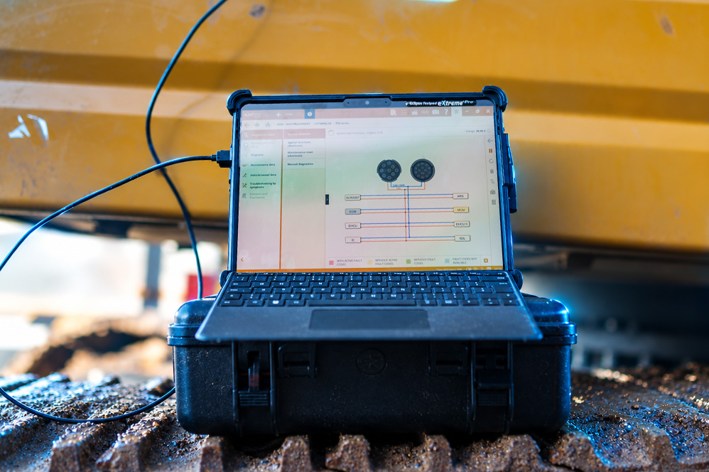
- Use wiring diagrams to isolate the affected section. Rather than testing the whole harness, use the vehicle’s wiring diagram to narrow the search to the specific circuit or connector serving the unresponsive module.
- Only then consider the ECU itself. If power, ground, fuses, wiring and the bus have all tested correctly, a fault within the control unit or gateway becomes the more likely explanation.
Working through these steps in order, rather than jumping straight to component replacement, saves time overall and avoids the cost of parts that were never the problem.
How Diagnostic Software Supports the Process
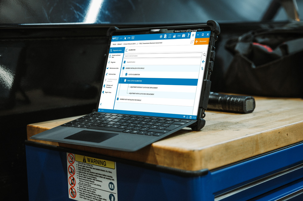
Good diagnostic software does not replace this process, but it can make each stage considerably faster. Tools that provide wiring diagrams and system topology alongside live diagnostics let a technician see exactly how a suspect module is wired into the network, which other systems share its power, ground or bus connection, and where connectors and splices sit along the harness, without needing to trace the loom by hand.
Guided diagnostic functions can also help by working through a structured test sequence for a no communication fault, prompting checks in a sensible order rather than leaving the technician to decide where to start. Software such as Jaltest, used widely across commercial vehicle workshops, includes this kind of topology and guided diagnostic support across a broad range of makes and models, which is particularly useful on mixed fleets where technicians may not be equally familiar with every manufacturer’s wiring layout.
Whichever tool is used, the value lies in giving technicians clearer information earlier in the process, so decisions about testing and replacement are based on evidence rather than assumption.
Final Thoughts
No communication faults can look intimidating, but they are rarely as mysterious as they first appear. Working through battery voltage, wiring, fuses, connectors and the CAN bus in a logical order, before considering the ECU itself, gives technicians the best chance of finding the real cause quickly and avoiding unnecessary parts replacement.
If your workshop is looking to reduce diagnostic time on faults like these, our technical support team is on hand to help, and our training courses cover exactly this kind of structured diagnostic approach using Jaltest software.