
In the world of construction, machinery is the backbone that supports various operations, from earthmoving to lifting, and from drilling to hauling. However, like all sophisticated systems, construction machinery is prone to technical glitches and issues, often indicated through fault codes. These fault codes, while helpful in diagnosing problems, can be a source of frustration if not adequately understood or if the response protocol is unclear. This article delves into understanding these common fault codes, the remedial measures, and the diagnostic tools that have revolutionised machinery troubleshooting, including the renowned Jaltest diagnostics.
Understanding Fault Codes
Fault codes are essentially messages sent by a vehicle or machinery’s onboard computer system, indicating a detected malfunction or performance issue. These could range from engine disruptions, hydraulic system failures, transmission issues, or other system malfunctions. For construction machinery, which often combines mechanical, hydraulic, and electronic systems, these fault codes are critical for timely intervention, preventing potential safety hazards, and avoiding costly downtime.
Common Fault Codes and Fixes

🔴 Electrical Fault Code 699-26 – Electronic cabin error code
Description:
- Error Warning Device overload
Alarm:
- Signal outside allowable range
Information:
- P006: OMD-Sensor cell A or B in
outside the beach
Error diagnosis:
- Check the signal routing line of the overload warning device
P006 pin 1 via fuse F013 (5A) to main fuse board 12V64A X2. - Check the signal routing line of the overload warning device
P006 pin 2 downstream of ground. - Check the signal routing line of the overload warning device
P006 pin 3, up to computer N004 pin 122. - Check the signal routing line of the overload warning device
P006 pin 4, to load sensor B008
pin A/3. - Check the signal routing line of the overload warning device
P006 pin 5, to load sensor B008 pin C/3. - Check the signal routing line of the overload warning device
P006 pin 6, to load sensor B008
pin B/3. - Check the terminal resistance at the CAN Bus.

🔴 Engine Fault Code 3516-2 – Aftertreatment #1 DEF Concentration : Erratic, Intermittent, or Incorrect
Comments:
- The ECM detects that the DEF Quality measurement received from the DEF Tank Sensor over the datalink is not within the acceptable range.
or
The DEF Quality measurement received from the DEF Tank Sensor has shown an invalid quality measurement within a monitoring window. - The code is logged if the DEF quality measurement does not resolve into acceptable measurement range after a time delay.
Troubleshooting:
- DEF Tank Sensor – Test
SMCS – 108T-038-NS
Use this procedure to troubleshoot the electrical system if a fault is suspected with the sensors. Use this procedure if any of the diagnostic codes in Table 1 are active or easily repeated.
Battery voltage is routed to terminal 4 of the tank header unit. The return is routed to terminal 3 of the tank header unit. The temperature, level, and quality signals are routed through the CAN C data link on terminal 2 (CAN C+) and terminal 1 (CAN C-). The ECM provides short circuit protection for the internal power supply. A short circuit to the battery will not damage the internal power supply.
If possible, the machine should be on a level surface before the following procedure is performed.
The tank header unit houses the DEF tank temperature, the DEF tank level, and the DEF quality sensors. The sensors are not serviceable individually.
Complete the procedure in the order in which the steps are listed.
| Table 2 | ||
| Troubleshooting Test Steps | Values | Results |
| 1. Check for Diagnostic CodesA. Establish communication between the electronic service tool and the ECM . Refer to Troubleshooting, “Electronic Service Tools”, if necessary.
B. Turn the keyswitch to the ON position. C. Look for active or logged codes. |
Diagnostic code | Result: A -12 diagnostic code is active.Proceed to Test Step 2.
Result: A 1761-2 (3131–12) code is active. Proceed to Test Step 4. Result: A 3516-2 (3100–2) code is active. Proceed to Test Step 5. |
| 2. Check for Battery Voltage at the DEF Tank HeaderA. Disconnect the harness at the DEF tank header.
B. Turn the keyswitch to the ON position. C. Measure the voltage between terminals 3 and 4 on the harness connector for the DEF tank header. D. Turn the keyswitch to the OFF position. |
Battery voltage | Result: The measured voltage is not equal to battery voltage. The fault is in the power supply wiring to the DEF tank header.Repair: Repair the faulty wiring or replace the faulty wiring.
Result: The measured voltage is equal to battery voltage. Proceed to Test Step 3. |
| 3. Connect a Replacement DEF Tank Header UnitA. Disconnect the connector from the DEF tank header unit.
B. Connect a replacement DEF tank header unit to the harness. Do not install the unit. C. Connect the electronic service tool. D. Turn the keyswitch to the ON position. Wait for at least 2 minutes. E. Check for -12 codes. |
DEF tank header replacement | Result: No -12 diagnostic codes are active.Repair: Install the replacement DEF tank header unit. Confirm that the fault has been eliminated.Result: A -12 diagnostic code is active.Reconnect the harness connector to the original DEF tank header unit. Contact the Dealer Solutions Network (DSN). |
| 4. Ensure that the Application is on a Level GradientA. If necessary, move the application to a level gradient.
B. Wait at least 2 minutes. Turn the keyswitch to the ON position. C. Connect to the electronic service tool. D. Use the electronic service tool to check the DEF level measurement. |
DEF Level | Result: The DEF level indicates a value between 0 percent and 100 percent.Return the engine to service.
Result: The DEF level indicates “Conditions Not Met” 2 minutes after the application has been moved to a level gradient. Proceed to Test Step 5. |
| 5. Flush the DEF Tank and Refill the DEF TankA. Turn the keyswitch to the OFF and ensure that the “Wait to Disconnect” lamp has switched off.
B. Flush the DEF tank and refill the DEF tank. Refer to Operation and Maintenance Manual, “Diesel Exhaust Fluid Tank – Flush” for the correct procedure. C. Turn the keyswitch to the ON position. D. Use the electronic service tool to check the DEF level measurement. |
DEF Level | Result: The DEF level indicates a value between 0 percent and 100 percent 2 minutes after the DEF tank has been filled.Return the engine to service.
Result: The DEF level indicates “Conditions Not Met” 2 minutes after the DEF tank has been filled. Proceed to Test Step 6. |
| 6. Inspect the DEF Tank HeaderA. Turn the keyswitch to the OFF position.
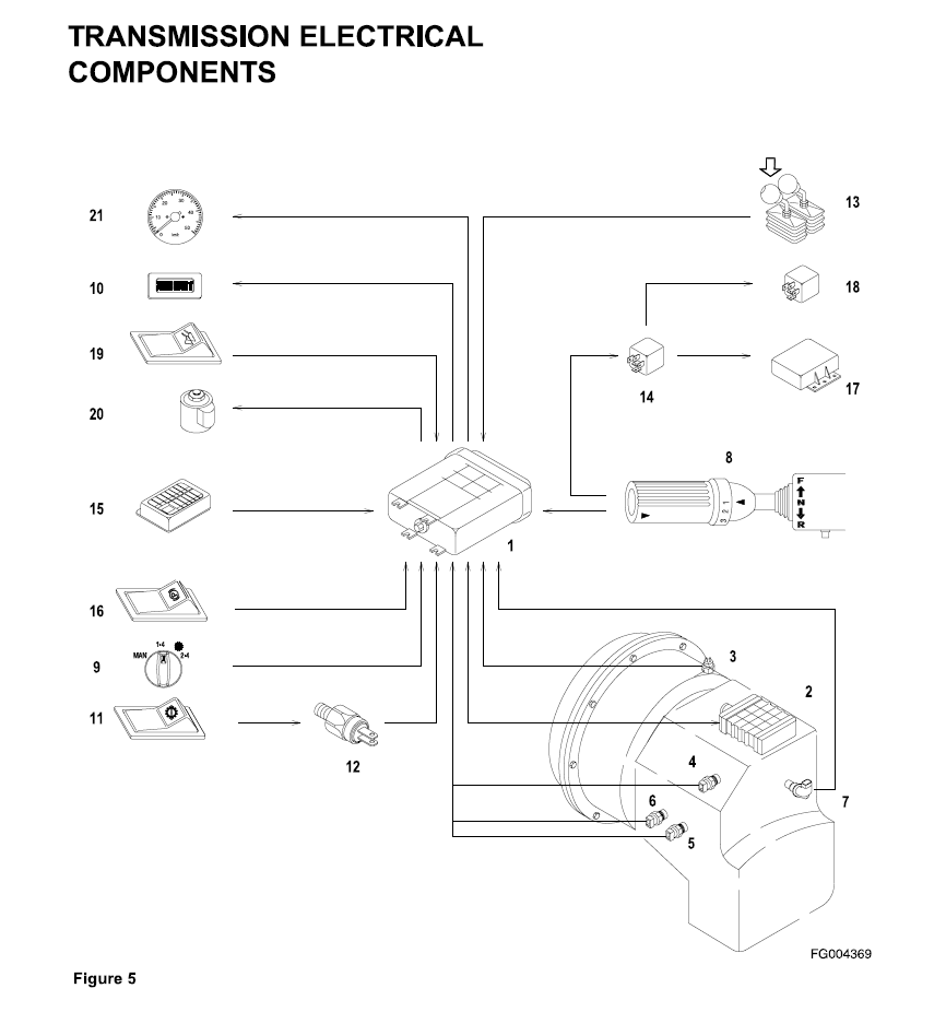
B. Remove tank header (2) from the DEF tank. Refer to Disassembly and Assembly, “Manifold (DEF Heater) – Remove and Install”. C. Inspect the DEF tank header for damage or debris to the sensor pick-up tube. |
Correct operation of level and quality sensors | Result: The level sensor is damaged or debris is present.Repair: Turn the keyswitch to the ON position. Wait for 2 minutes. If the DEF level in the electronic service tool indicates “Conditions Not Met”, replace the DEF tank header.
Result: The DEF temperature is greater than 0° C (32° F) and the 3516-2 (3100–2) code is still active. Repair: Replace the DEF tank header. |

🔴 Hydraulic Fault Code C151A-13
DTC – FTB Description:
- Auxiliary Changeover Solenoid Open
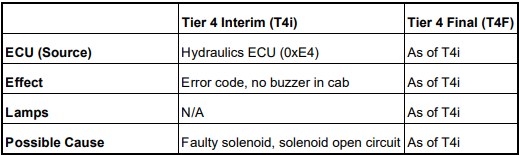
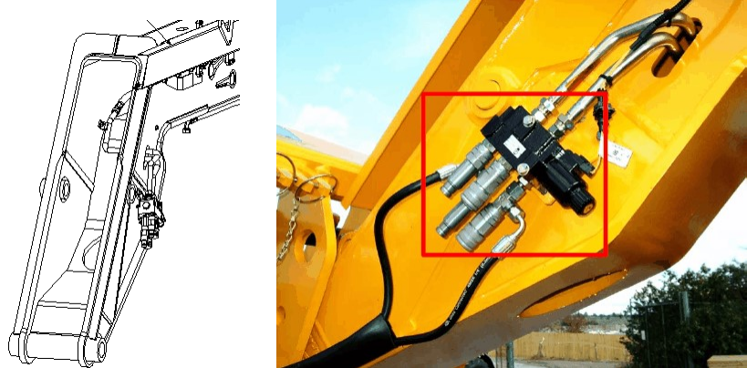
Location:
- The auxiliary changeover solenoid is found near the the auxiliary hydraulic outlets, at end of the boom.
Note:
- Due to the many variants of suppliers and types of hydraulic control, the exact location of a valve block cannot be specified by these help files. Below is an example of the location of an auxiliary changeover solenoid.
Service Procedure:
Important: Stop the engine and let it cool before you start work. Do not start the engine during the service procedures.
1. Check for water ingress or debris inside the terminals of the connector. Could be due to pressure washing, bad connector seals or loose connectors.
2. Check the harness for integrity and ensure it is routed correctly. Refer to Electrical Connections.
3. Complete the full procedure for testing a Solenoid in the component information page.
Related DTC – FTBs


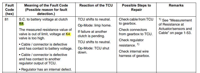
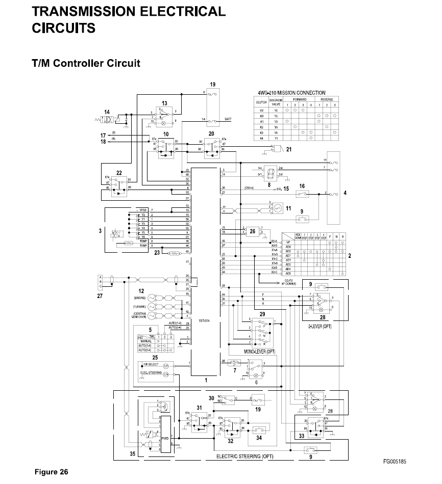
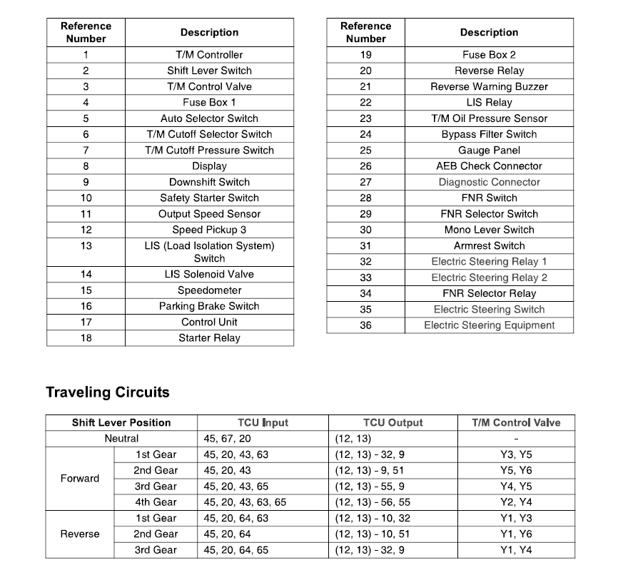
🔴 Transmission Fault Code 81
Diagnostic Tools Revolutionising Troubleshooting
Modern problems require modern solutions. The use of advanced diagnostic tools has significantly streamlined the process of identifying and rectifying machinery faults. These tools interface with a machine’s electronic control module (ECM), providing detailed diagnostic information beyond what’s available through standard fault codes.
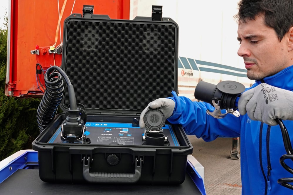
Jaltest Diagnostics: A leader in multi-brand and cross-system diagnostic solutions, Jaltest offers comprehensive equipment that allows for the thorough diagnosis of mechanical issues in construction machinery. With its ability to perform advanced functions such as real-time data monitoring, interactive diagrams, and system tests, Jaltest stands out as a preferred tool for many professionals. It also boasts extensive fault code libraries and troubleshooting guides specific to various machinery models and systems, making it invaluable in quickly deciphering and responding to fault codes.
OEM Software Tools: Many machinery manufacturers offer proprietary diagnostic tools designed specifically for their equipment. These tools, while not as versatile across different brands as Jaltest, provide in-depth information and analysis based on the manufacturer’s intimate understanding of the machinery.
Handheld Diagnostic Devices: For field repairs and situations demanding immediate attention, handheld diagnostic devices are invaluable. They offer a balance between detailed analysis and portability, providing essential fault code information and basic troubleshooting steps to guide on-the-spot interventions.
Telematics Systems: Some newer construction machinery comes equipped with telematics systems, offering GPS tracking, remote diagnostics, and real-time operational data. When a fault occurs, these systems can sometimes even alert support staff back at the office, enabling proactive maintenance scheduling.
Conclusion
Understanding the implications of fault codes in construction machinery is vital for operators and maintenance personnel, contributing to efficient operation, reduced downtime, and prolonged equipment lifespan. While professional intervention is often necessary for complex faults, having a fundamental understanding of these codes and the role of diagnostic tools can significantly expedite the troubleshooting process. With advancements in technology, particularly in comprehensive systems like Jaltest diagnostics, the realm of machinery maintenance is more equipped than ever to tackle the challenges of modern construction demands.